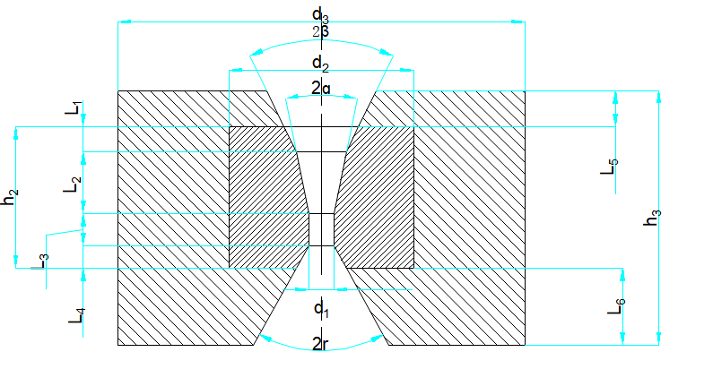
Wire drawing die is the main tool to process wire drawing, which is directly related to the surface quality of the wire, energy consumption in the drawing process, production operation rate and mechanical properties of the finished wire, and even the service life of the wire drawing die will directly affect the cost of the product. Therefore, the correct choice of wire drawing die material, the reasonable design of die hole form and size, mold structure, mold repair process and processing accuracy, etc., will play an extremely important role in the production of wire.
Drawing die can be divided into the following categories due to its use, materials used and structural types:
According to the geometry of the die hole, there are round wire drawing dies and square, triangular, hexagonal and other special-shaped wire drawing dies.
According to the mold material, there are alloy steel die, carbide die, natural diamond (single crystal) die, artificial polycrystalline diamond die, corundum ceramic wire drawing die.
According to the mold structure, there are integral mold, combined mold, assembly mold and so on.
According to the working characteristics of the mold, there are sliding contact die, roll drawing die (rolling contact die), rotating die and so on.
As shown below the drawing die, it is composed of two parts: die core 1 and die sleeve 2. The mold core is made of hard alloy (there are also natural diamond, polycrystalline diamond, etc.), and the mold sleeve is generally made of medium carbon steel, carbon tool steel turning or high carbon iron powder pressing and forging. Although the core material has high hardness and compressive strength, its tensile strength and impact resistance are poor, and its brittleness is large. Therefore, the mold core can not withstand excessive tensile stress and shock force. In order to make the mold core not broken in the work, it is necessary to add a steel sleeve in the mold core, the steel sleeve to the mold core a certain compressive stress, offset or reduce the tension stress of the mold core, in order to increase the strength of the mold core to prevent rupture.
The size code of each part of the wire drawing die is shown in the table below
Description | Name of Each part | GB6110-85 No. |
Wire Drawing Die
| Die core outer diameter | d2 |
Outer diameter of die case | d3 | |
sizing zone diameter | d1 | |
Core height | h2 | |
Case height | h3 | |
Working cone Angle | 2ɑ | |
Working area height | L2 | |
Lubricating zone cone Angle | 2β | |
Exit zone cone Angle | 2r | |
Mold inlet area height | L5 | |
Core exit area height | L4 | |
Die sleeve exit area height | L6 | |
Die hole caliper with height | L3 |
The geometry of the die hole is divided into five sections: entrance zone, lubrication zone (compression zone), sizing zone and exit zone. The five sections are cylindrical except for the caliper area, the other four sections are truncated cone shape, and each section is smooth transition
